I know what everyone’s thinking. “Oh my Toshko why did you wait so long to bring back the blog I had no idea what to do during quarantine without your blog and thank you so much for bringing it back because now my world is complete.” I know I know. Don’t worry, it’s back.
All jokes aside, now that we’re starting to do some more things – both virtually and in-person – I wanted to bring back the blog so we can highlight, record, and learn from what we’re doing.
Summer Recap
Over the summer, things were more stagnant than usual, but that did not stop us from still accomplishing some things. Most notably, a couple design team members participated in two CAD-a-thons, each lasting one week. During that time frame we got some good practice with designing a full robot and all the intricacies of each mechanism.
Our marketing team also got started during the summer on some grants and sponsorship ideas. So far several promising grants have been submitted and we await a response from them. We have also received several grants from some companies, which has given us a much-appreciated boost.
Post-Summer and Off-Season
Now that the school year has started, we’ve also begun working on several projects and developing skills. The largest of these is probably the current design for our 2021 season robot. Although FIRST has said there will likely be no in-person competition next year, there will still be many opportunities to develop a new robot for possible in-person competitions and virtual submission. So, in preparation for an even better season than this one, we decided to use the knowledge that Infinite Recharge will be replayed to start designing an even better robot for 2021.
Torpedo (our 2020 robot) was great robot. Arguably the best the team has made. However, with the goal to always be the best robot on the field, there were several improvements to be made. So, several profiles were conjured to find the optimal way to address critical hardware problems.
John’s Profile
While a little scarce on detail, John’s profile provides a preview of an extremely agile robot which could be very effective in competition. A swerve drive base provides quick movement and easy side-to-side alignment for shooting more accurately. Additionally, a continuously adjustable hood would provide for easy angle adjustability for shots. No climb was CAD-ed but the profile planned to have a climb mechanism as well.
Keshav’s Profile
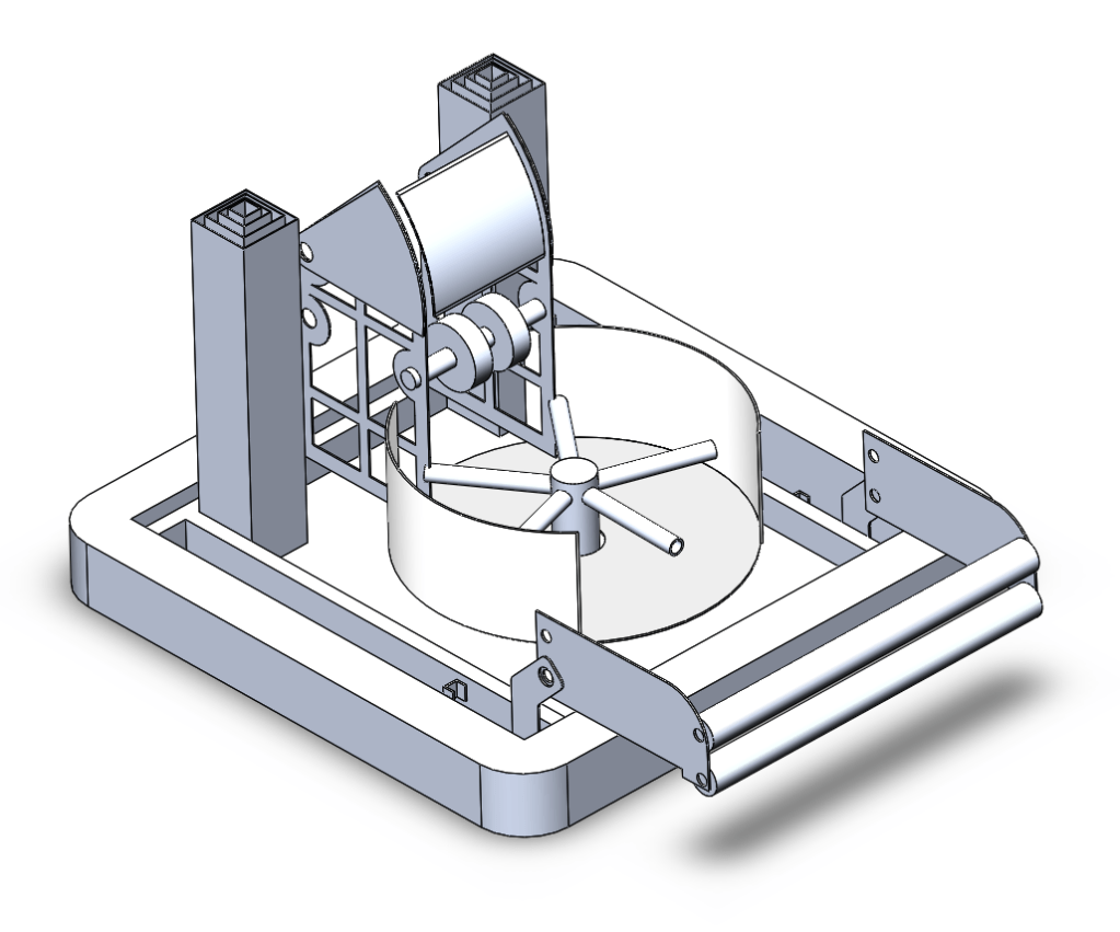
Keshav designed his profile to address many of the problems he saw with Torpedo. It allows for an easier ball intake by having a serializer (the circle in the middle) accept multiple balls at one time and sort them into a neat line. Then, they are – one by one – brought up to the shooter where an adjustable hood adjusts the angle of release of the ball. The side to side motion, in Keshav’s profile, of shooting adjustment would be handled by the drivetrain. For a climb, the profile presents two telescoping arms that extend all the way and lift the robot a considerable amount.
Toshko’s Profile
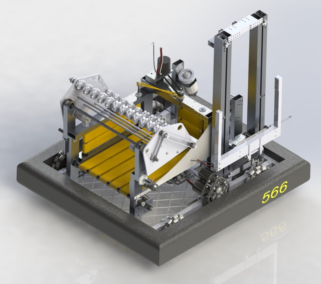
My (Toshko) profile captured similar characteristics and solutions to problems as Keshav’s with a few distinct tweaks. Most notably, my shooter has a turret controlling the side to side motion of shooter adjustment rather than rely on the drivetrain. Additionally, my climb closely resembles our flip-up elevator climb on Torpedo but, instead of an elevator, two telescoping arms would flip up and grab onto the bar. Finally, one small detail is that instead of dividers separating the balls in the serializer, my profile uses holes cut in a bottom panel to allow balls to settle down.
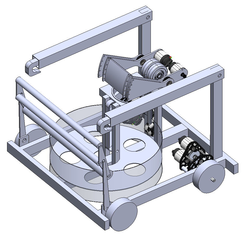
In the end, my profile was chosen by the design team to further develop and design. Tasks were divided the design process started. So far, the drivetrain, most of the climb, and initial sketches of the intake have been completed.
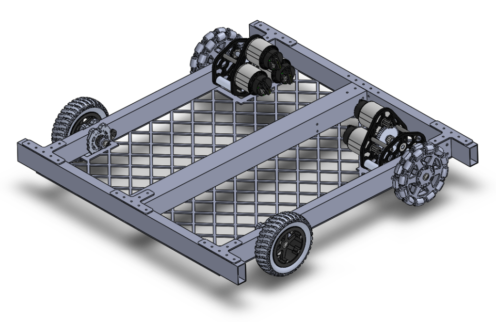
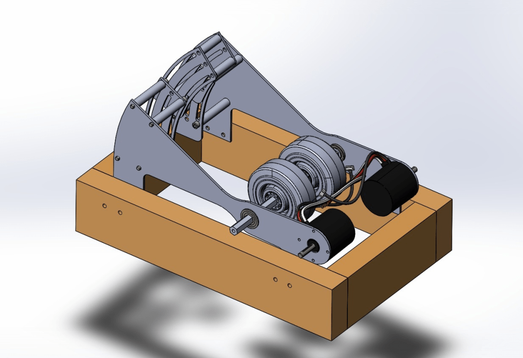
The drivetrain improves upon Torpedo’s due to it’s much shorter nature. It closely resembles that of our 2019 robot “Flipper” in size and functionality. The same wheels, gearboxes, and general architecture that we’ve used for the past two years are implemented again. A beam down the middle provides a structural base onto which the shooter tube and serializer (or spindexer if you may) can easily mount. The position of the wheels as you see them in the screenshot may change as we decide which position would be more suitable for the omni wheels.
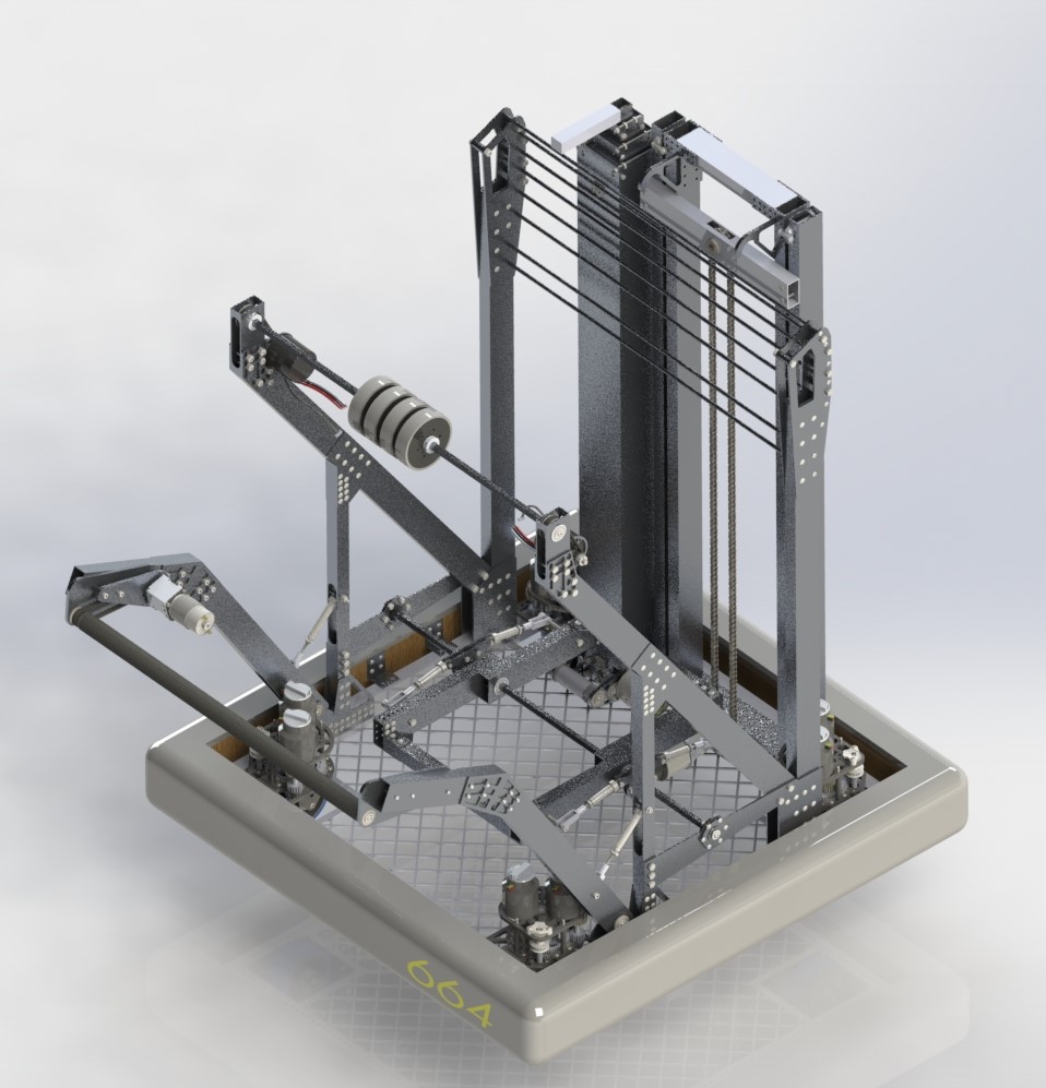
The each side of the climber has a telescoping arm with one inner stage and one outer stage. The outer stage pivots on an elevated beam at the back of the robot after which the inner stage extends upward to grab onto the bar. Two constant force springs extend the inner stage upwards while a rope attached to the bottom of the inner stage travels down to the base of the drivetrain and spools on a winch. Once the robot is hooked onto the bar, a two motor winch should provide a 1 second climb. Several small details – such as a ratchet, diagonal supports, and a few minor tweaks – still need to be CAD-ed. For those interested, these are the calculations for the climber and its sub-mechanisms. They have not been peer-reviewed yet so if you find a flaw, feel free to point it out.
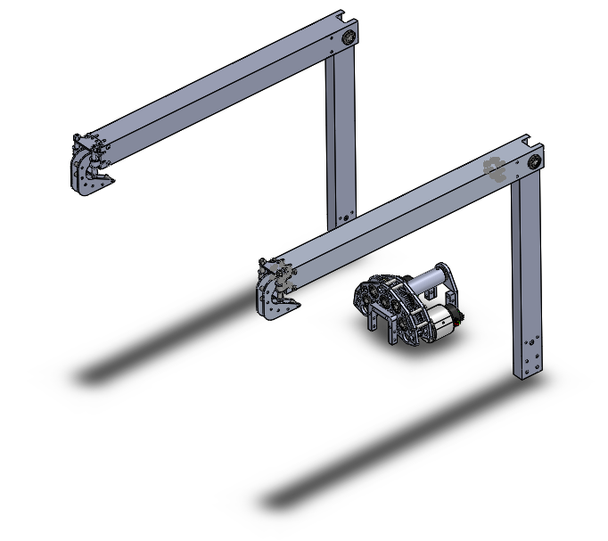
The climber assembly 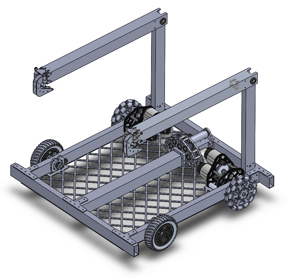
The climber on the drivetrain
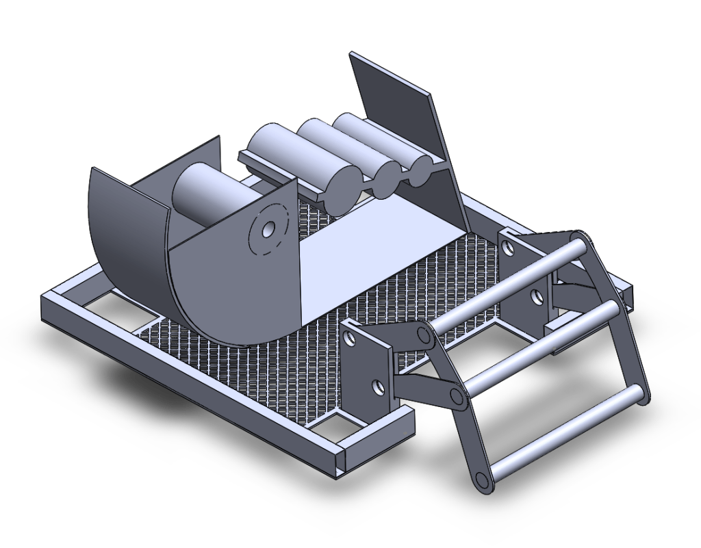
Initial geometry sketches for the intake are also almost done. These are important to create in order to properly design an intake that we know will control the ball and guide it into the robot the way we want it to. Additionally, they provide a sound framework for the CAD of parts so that each part is based on the ball path and not simply on dimensions.
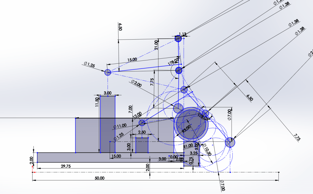
The final element of the robot design that is in progress at the moment is our shooter. However, in order to create an effective shooter, we first wanted to create a prototype that will hopefully give us a range of angle values for our hood.
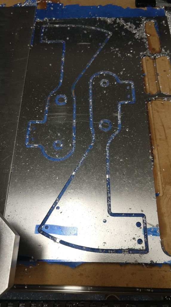
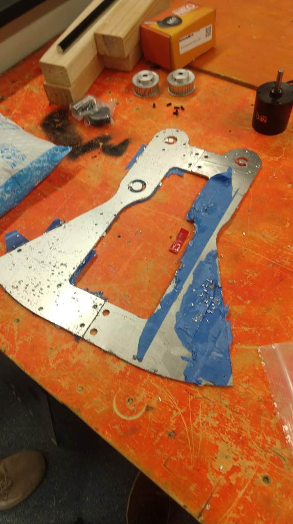
So, as we had our second in-person meeting on Thursday, we fired up the CNC and managed to churn out some nice plates to be used for our prototype. These were all made out of 1/8″ spare aluminum sheets. We will use two Neos to simulate the power of two falcons on our shooter. Two 4″ colson wheels will be used with about 1.5″ compression on the ball for initial testing. However, many wheels will be tested to find the best option.
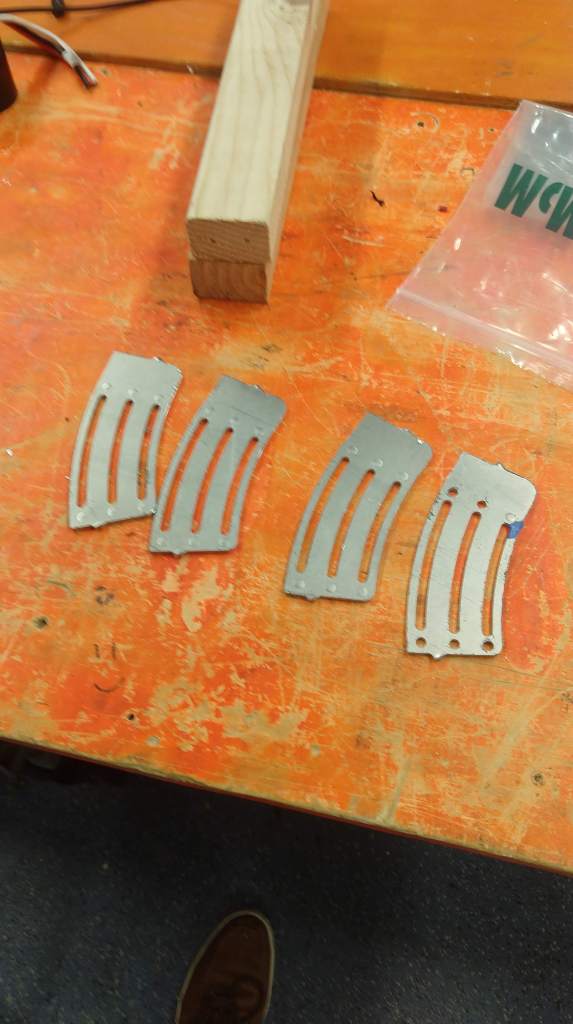
The next time we meet, the shooter prototype will be assembled and hopefully tested. Since we do not have an extra PDP or RoboRIO, we will use Flipper’s electronics board and the wiring for its intake motors to run the two Neos on the prototype.
Finally, we also are seeking to vastly improve the software of Torpedo. Key issues deal with the PID on our tube adjustment and shooter wheels. Particularly, we hope to reach a consistent rpm on our shooter wheels in order to maximum consistency in shots. This, paired with a lot more limelight development, should allow us to fix the wide array of shooting problems we had at competition.
On the topic of limelight development, I wanted to give a brief overview of an interesting problem we recently solved. A reach goal of ours since the season has been to enhance our limelight capabilities such that our robot can, at any point on the field, adjust to the right tube angle and shoot the balls into the port. However, the difficulty of the implementation of this idea on our robot comes with the fact that, as our robot changes its release angle, it also changes the distance and height of the release point. Therefore, when trying to solve the projectile motion physics problem, we are left with an unsolvable equation. In order to solve this, a small program was written to, for each theta value for the tube angle, compute the value of the left side of the equation and the right side of the equation and find the theta value at which the difference between those is smallest. This process is repeated for each possible distance. The physics calculations for the situation can be found here. When completed, the graph of the various distances and the various corresponding theta values looks like this:
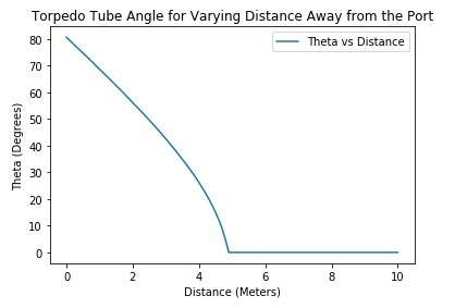
At one point, the velocity is not high enough for the ball to go into the port and so we get a 0 value since it’s impossible. This graph is not necessarily correct as the constants (velocity and various field and robot measurements) are heavily approximated, but it gives a general idea of what continuous, limelight-based tube adjustment would look like. This should hopefully serve as a useful tool to implement once we improve our limelight recognition and ensure shooting consistency.
So, that about wraps up almost everything that’s been done and being done so far. I hope to write another detailed blog analyzing Torpedo’s successes and flaws soon. And, finally, since I know you’ve probably been wondering how Torpedo’s been doing, I leave you with this video:
Just to calm everybody’s nerves, the climber in the video didn’t work because one motor wasn’t engaging with the screw. It was a simple problem of a loose coupler and, when the coupler was tightened, the robot climbed effortlessly. Additionally, the intaking in that video is smoooooooooooooooooooooth (much smoother than at competition).
That’s all for now folks. Hopefully more to come later. Peace out. ✌️

Wowie
LikeLike