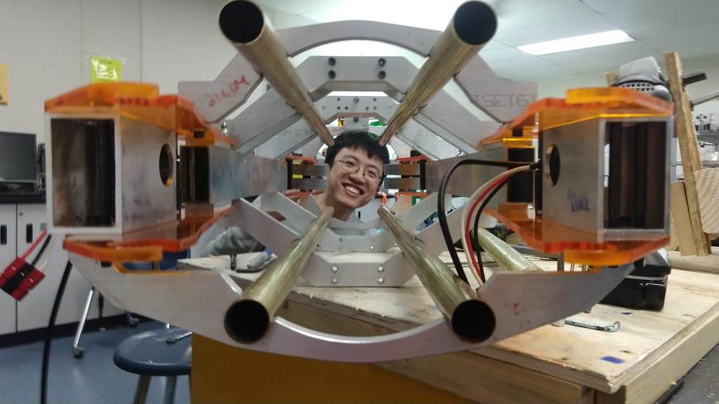
Over the past couple of days we’ve continued working on finishing up climber pieces as well as completing, testing, and attaching the tube and intake onto the chassis. We were able to get the shooter and intake plates for the tube attached on Tuesday and some of the wheels and motors that go along with that as well. We also worked on welding the polycord together and attaching it along the length of the tube (a process that required a good amount of force). All in all, the tube was finished before 6pm yesterday.
The tube at the end of Tuesday (with Gary’s face in it as well).
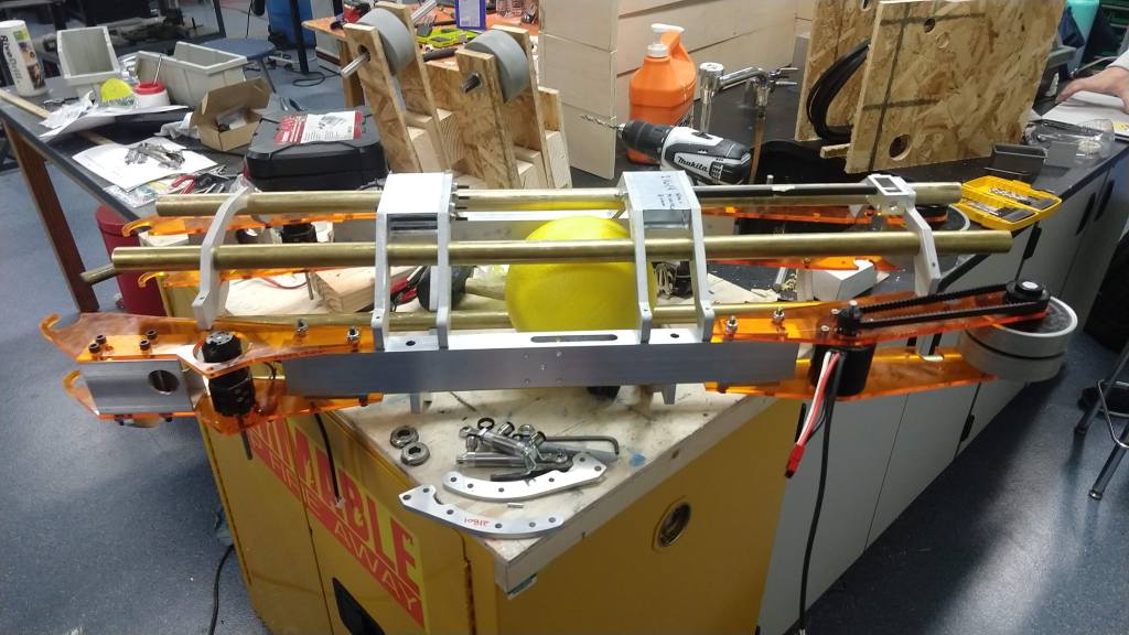
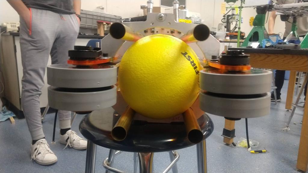
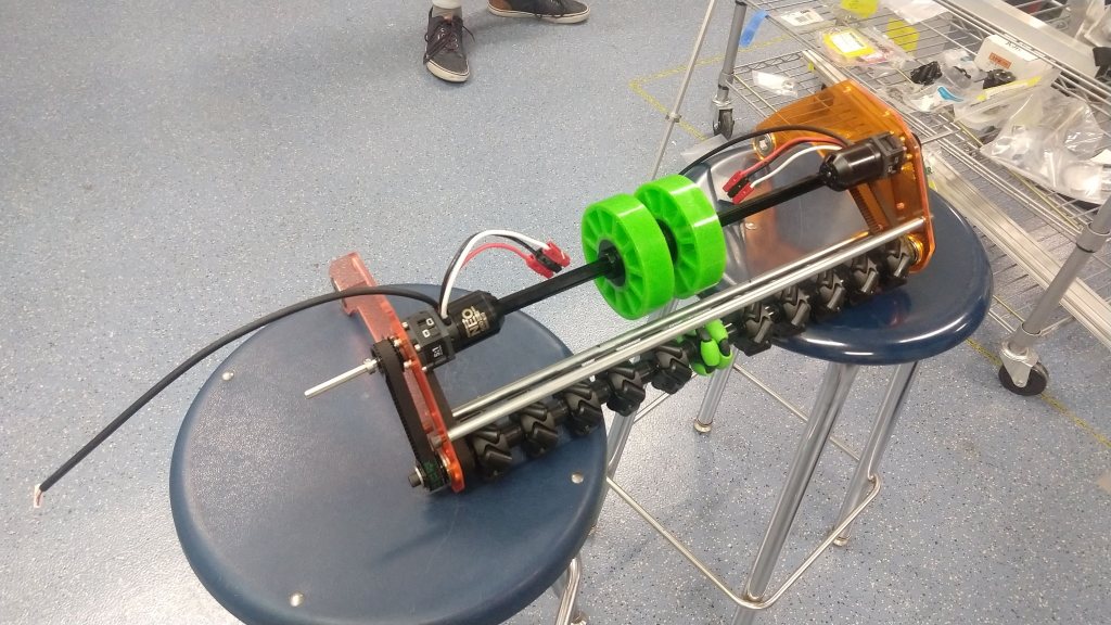
The tube in its full completed state as is now (technically there are two belts we have to add but that is a 5 minute job).
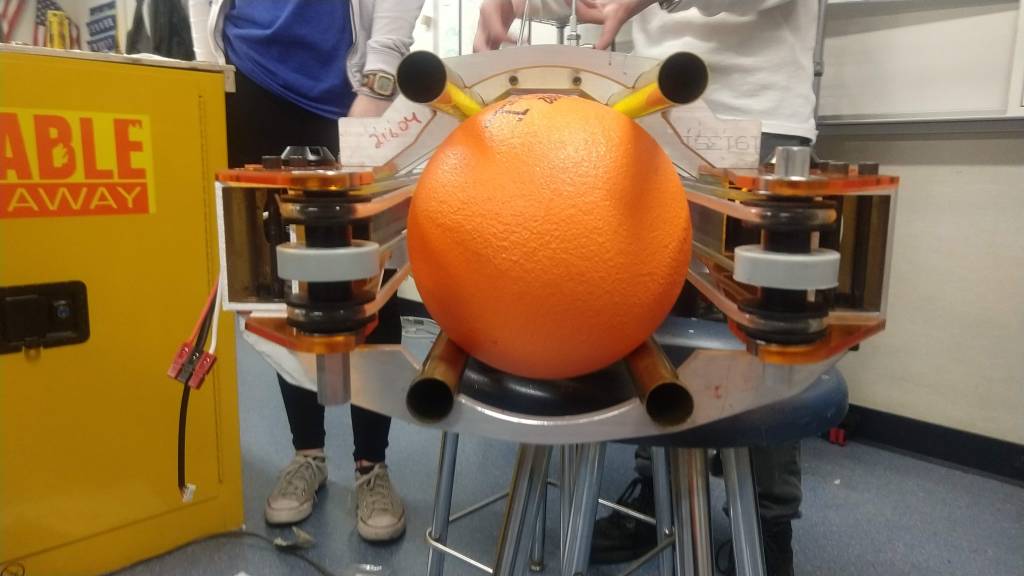
At the general meeting yesterday we were also able to use the completed intake to Frankenstein it to the electrical system. We wanted to test out whether the compression on the balls was right for shooting them out. It turns out that Gary’s eyeballing seemed spot on. The balls shoot out fine and it doesn’t seem like adjustment will be necessary. In addition we tested the belt system using some drills and, if both sides are powered at the same speed (which they will be with motors), it will work perfectly.
The first test of our shooter outside. The angle is a little low but it seems to work just fine.
The second test of our shooter. It is now at a slightly higher angle and you can see the change that results.
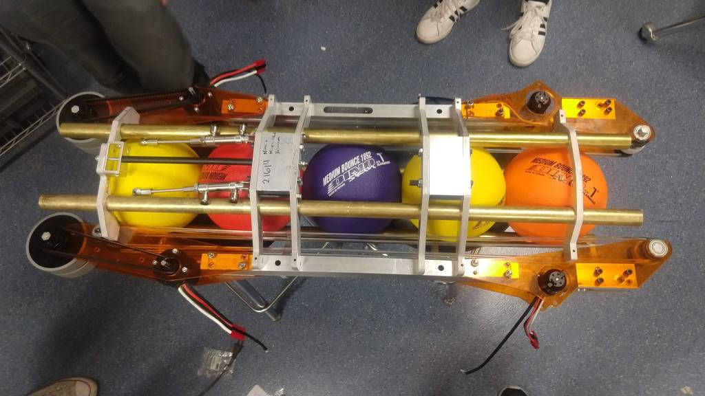
Just a sample test of two balls going into the tube via the belts. We tested with all 5 and it still works.
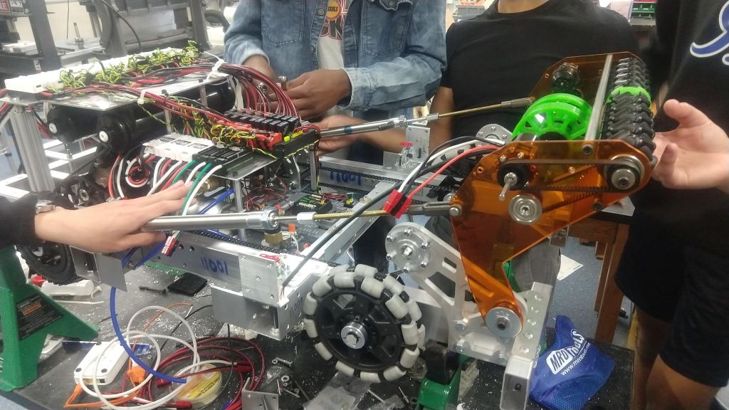
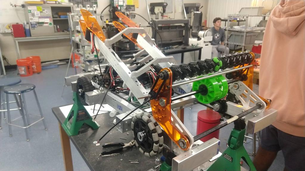
The intake was also attached onto the robot and pistons added to it as well. We have not wired or tested the intake and need to do so as soon as possible as the geometry might need some adjusting as well. However, if all goes well, the only things we will have left to do for the intake and tube will be switching the lexan plates for metal.
A picture of the intake with the pistons that will extend it. So far, everything seems to fit in very nicely.
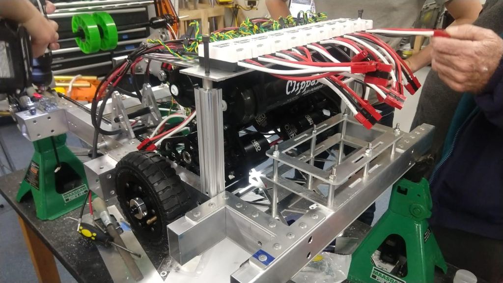
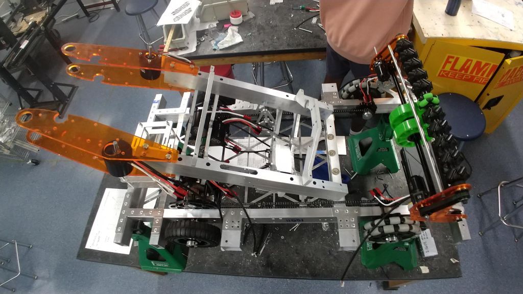
Electrical also had a lot of progress the last couple of days. The electrical board was finished and mounted to the robot (as you can see above). As soon as we attach the tube (which should hopefully be tomorrow) we will get the intake and tube wired (total of 7 motors) and hand off to software for testing. If need be we might also have to add some weights to simulate the weight of the climber (for software to test with the right weight) but it shouldn’t be a big problem.
Here’s a picture of the top plate of our electrical system which contains a LOT of spark maxes. You can also see our air cylinders underneath.
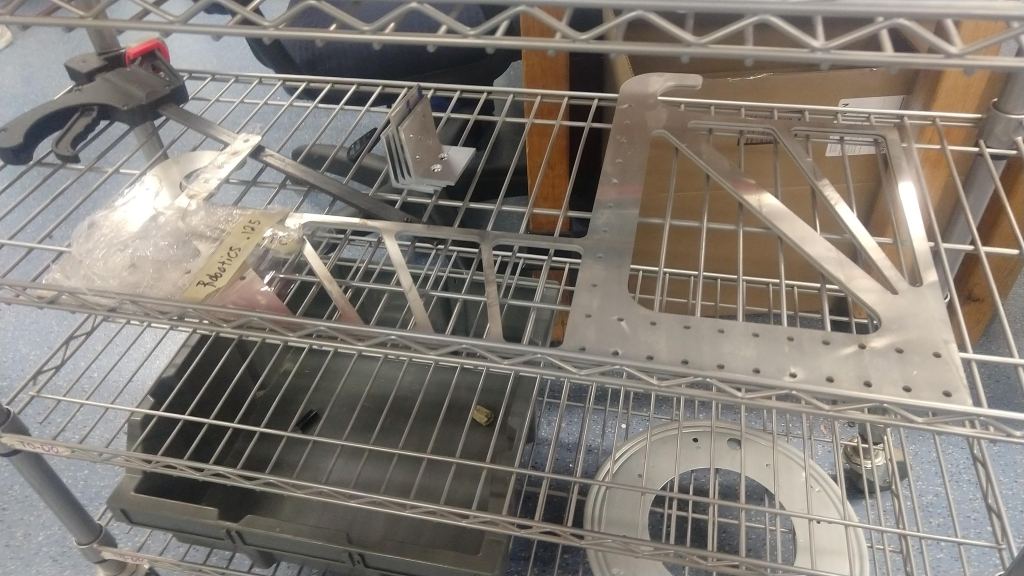
On a slight side not we got our hooks for the climb from waterjet and they look really cool. We hope to assemble these onto the climber as soon as possible.
The big plate that contains both hooks for the bar. One for when we’re climbing but won’t be level and one for when we’re climbing with another robot.
More videos and photos to come as we finish up the robot and software starts to test. At this point they have the code finished for the robot but still need to test out ball and tape tracking as well as run pathweaver paths to test out autonomous options. For now I’ll leave you with this funny video.
I could do more. But I preferred to stop at an even 10. Beni couldn’t do any (just kidding he did 11).
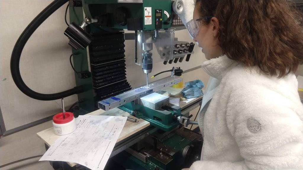
We started the day with the primary goal of attaching the intake and tube onto the robot and wiring the robot. Some parts still needed to be made for the tube adjustment mechanism and several parts tapped and/or turned (done on the lathe) for the tube and intake. We started off and were able to finish several pieces like the tube pivot blocks and lathing the screw for the adjustment mechanism. We were also able to get the CNC to work and make pieces throughout the day but more on that later.
At the end of the day, we ended up being able to basically finish all the pieces for the tube, tube adjustment, and intake, with a few exceptions. Various sizes of hex shaft for the intake and tube were cut out of hex stock with a hole in the middle but were never tapped. This will have to be quickly done first thing on Monday so that assembly can continue. However, despite this, progress was great. The intake was completely assembled (but not attached to the robot) and the tube is about halfway assembled. Because of the extra time we are getting all throughout the week to work, we will be able to finish assembly (and hopefully also be able to wire the robot) on Monday.
Pictures of the tube and intake in their current state. Turns out I was wrong about the orange being just a film we would pull off. Oops.
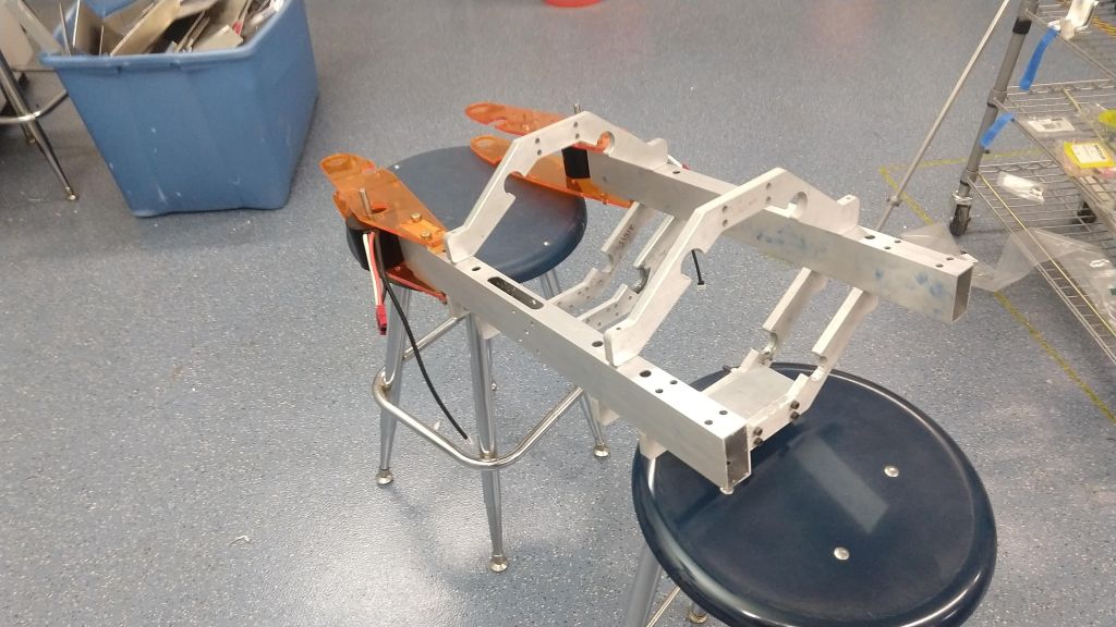
The intake and tube placed roughly how they would be on the robot (nothing is secure yet).
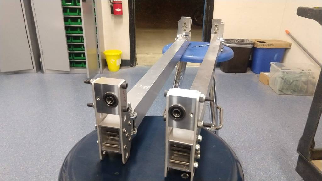
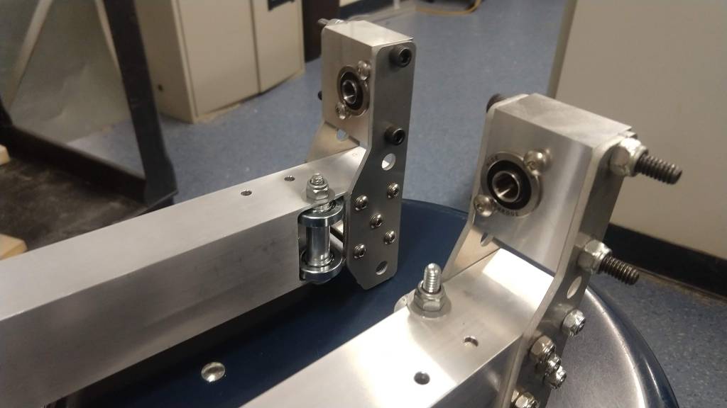
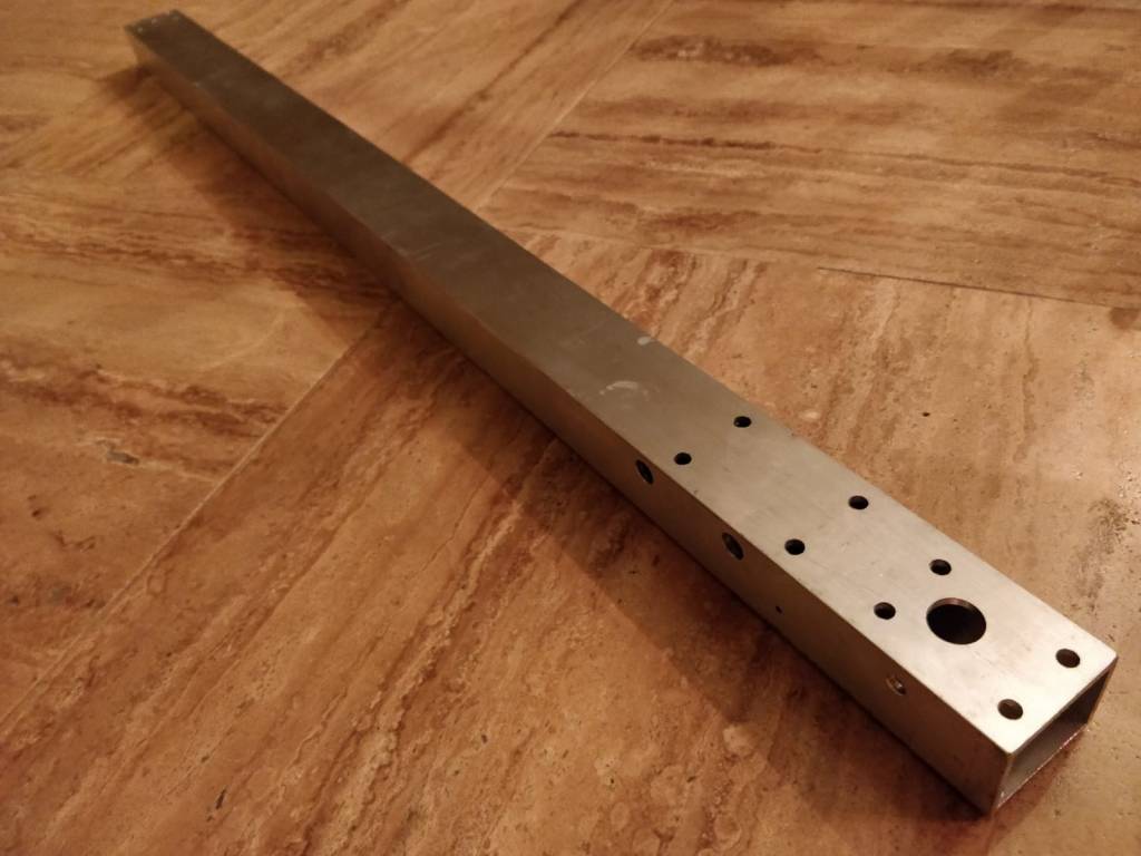
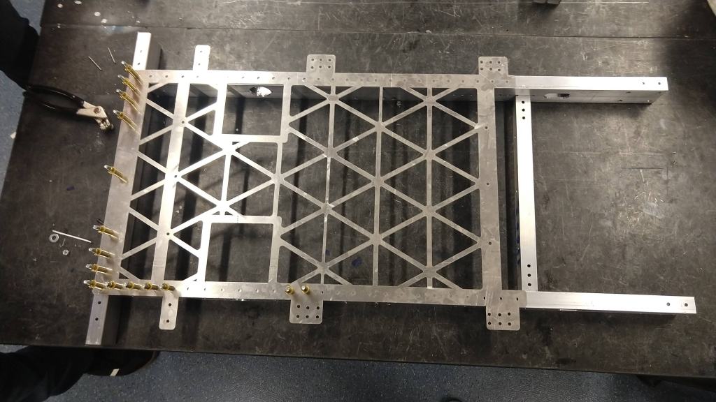
In addition, we also had our first two climber beams for stage one come in and assembly started for them as well. Throughout the first half of this following week we should be able to complete all the pieces left for the climb and assemble it off the robot. Placing it on the robot should be a simple matter of slipping a hex shaft through.
What we have done for the climber so far. These will both have a long lead screw going through them to run the second stage up and down.
In addition to building the robot, build also worked on finishing the intake prototype (prior to putting the mecanum wheels on the actual intake). They were able to test it now from two sides and with a cutout of sorts in the middle for the ball to go through. Although the build kids did not test jamming with multiple balls (which was the original purpose of this), they were still able to prove that one ball can smoothly go through. We should, in any case, still be able to test ball jamming in a couple days with the actual robot.
Here you can see the centering we hope the intake on the robot will accomplish when it intakes a ball from the side.
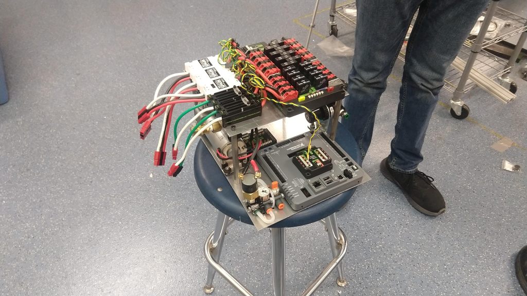
Electrical was also working today and had significant progress with the board. It seems to be almost complete with only a couple tweaks needed to make it fit inside the robot. Everything is a tight fit this year within the robot because of the tube taking up so much space. When wiring, electrical will also have to make sure that all the connections are solid so that we don’t have the same problems as last year. Then we had consistent issues with wires disconnecting during matches that persisted throughout the season. This was mostly a product of the Neo motors’ many wires, but also of some bad crimps we had. Things should be much improved this year though as we use Anderson connectors and zip ties along with them. We will also be tightly securing out encoder wires which were a big problem last year because of the fragile extension connectors.
The electrical board as completed so far. There is, however, another plate not pictured which contains most of our spark max controllers.
Now I also want to talk a bit about the CNC. Over the past couple of weeks we’ve been trying to tune it and get it to work just right and we were just now able to do it. I’ll go over some of the lessons we’ve learned and things that must be done to have the CNC work properly.
It all starts with the programming and many lessons were learned there first. The largest of them all being the speed, plunge rate (how fast it goes up and down), and the feed rate (how fast it moves side to side) of the bit. We found that 13,000 rpm with 5 in/min plunge rate and 30 in/min feed rate (although a slower feed rate might do the job too) works the best for the 0.25 in bit (which is currently what we’re using to cut all our pieces).
We also realized that the ideal order for making parts is going from the inside out. That is, drill the holes first, then make any “pools” (cutouts in weird shapes on the inside of the piece), and finally cut out the outline. That way the piece doesn’t move when you’re making the insides and everything is basically already done when you’re cutting it out.
Another final note about the programming is the depth which you cut. For some reason the CNC is off by a bit (depth-wise) and when programming it you have to set the cut depth to 0.01″ less than you want it (so if you’re cutting 0.25″ material, set it to 0.24″ cut depth). This way it goes right through the metal and doesn’t sacrifice on tab height.
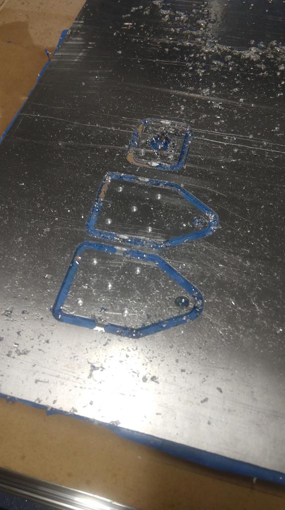
Now if we look at the actual physical setup, we learned a lot of lessons there as well. First and foremost, the masking tape adhesion method (where you stick masking tape to the table and the bottom of the piece, cover the back of the masking tape with gorilla glue, and then stick the plate to the sacrificial board) works the best when every bit of the entire sheet of metal (with special emphasis on the area underneath where you will be cutting the piece) is covered and done with extra care. We cut pieces out of three different materials over the course of the whole day and there was not even the slightest movement in the piece. Making sure both sides are covered in glue rather than doing one side in glue and the other in spray adhesive worked the best for us.
In addition to this, we also saw that a hefty use of WD-40 worked perfectly as machining oil for the bit. We made sure to cover the area where the cut would be done with WD-40 right before starting the cut and it made all the pieces have a nice finish and excellent cut quality.
The final thing has to do with the way we drill smaller holes. We found that the one flute 0.25″ bit works great for holes >0.25″ and for cutting our perimeters, but we were also able to re-purpose a 3/16″ end-mill we had with a 3/8″ shaft diameter and put it in our 3/8″ collet. We used this only to drill out holes (although in theory it should be able to cut more). Then, if we need holes that are greater than 3/16″ but less than 0.25″, we can just drill out the 3/16″ hole by hand.
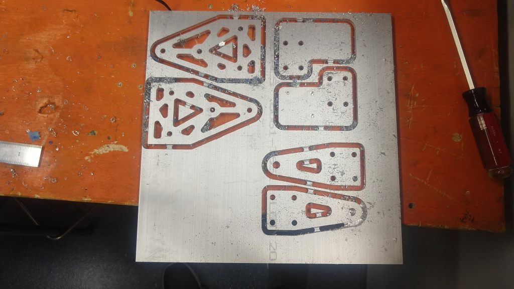
All in all, these lessons led to some pretty nice pieces being made on our CNC today.
Some pieces on and off the CNC after they’ve been cut.
A video of the CNC cutting the outline for one of our pieces today. Apologies for the vertical video. Also it’s very loud so you might want to mute it.
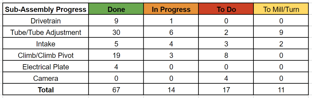
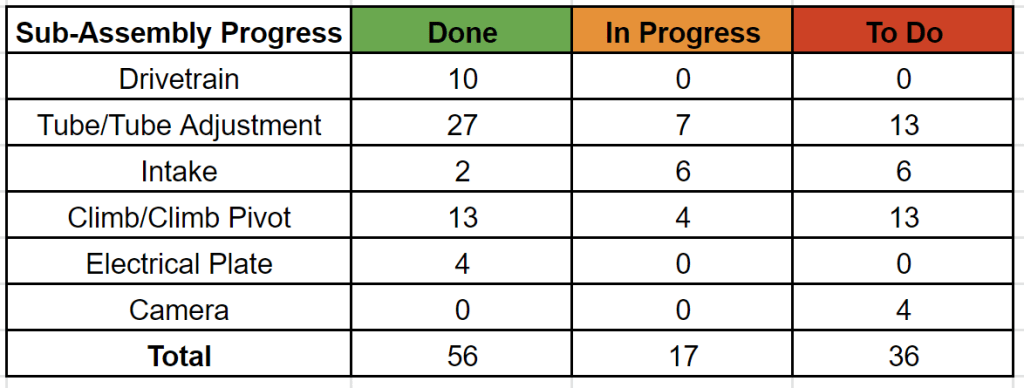
Overall progress for the robot is good as well as we turn our heads more towards the climber. You can see that things are in their final stages and that there are only a couple more parts to do and a little bit more assembly to complete. Again, this is rough and some parts are done that aren’t marked and some not done that are marked accidentally, so take that error into account.
The progress of various parts on the robot. “To Mill/Turn” means it’s been cut but it needs one more additional step done.
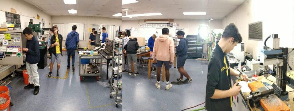
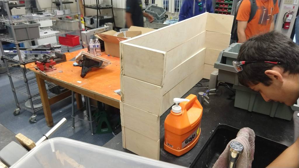
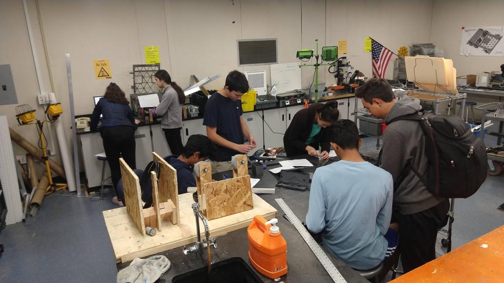
Finally, I leave you with one final picture to recap the day of the build team hard at work.
Every day we’re getting closer and closer to that mid-deadline of completed tube and intake assembly. Today we were fortunate enough to get to stay until 5 and because of that a lot of progress was complete.
Build-wise we were able to complete the other tube side beam and start drilling and tapping holes for the angled plates that hold the tubes on the tube. We were also able to start assembling a prototype to test ball jamming in the intake. Both the drilling/tapping and the intake prototype should be finished tomorrow.
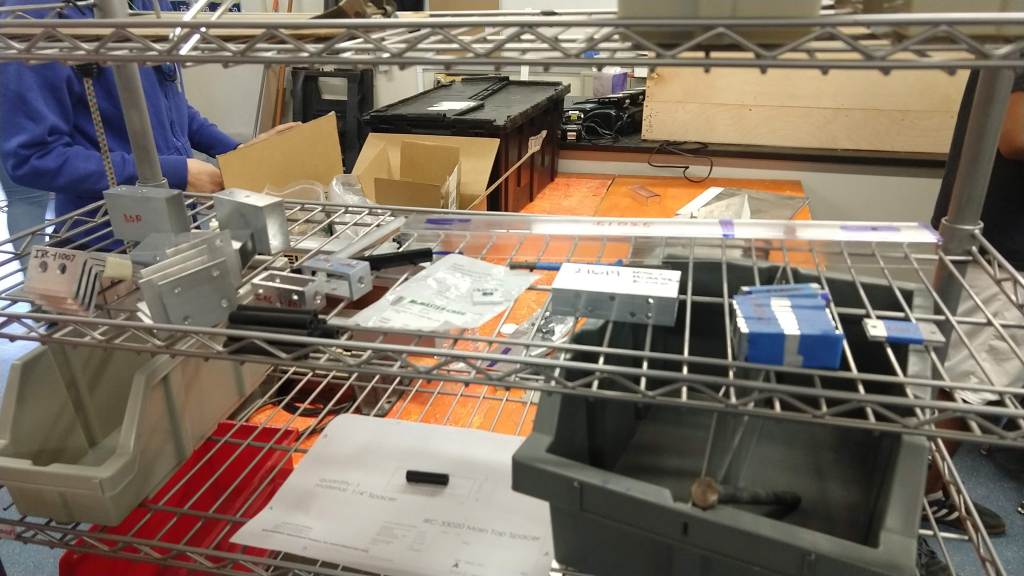
Mr Korol also got one piece of tubing for the climber done at 3D Systems as well as prototype lexan plates for the intake and tube. This means that once we finish up a couple more pieces tomorrow, we will have everything we need to assemble the tube and intake. If we keep the same pace, the climber should be assembled mid to late next week (but it would not take away from software time as they will have everything except the climb to test with).
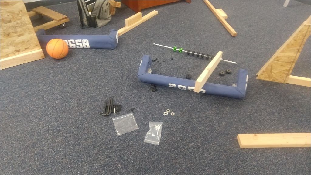
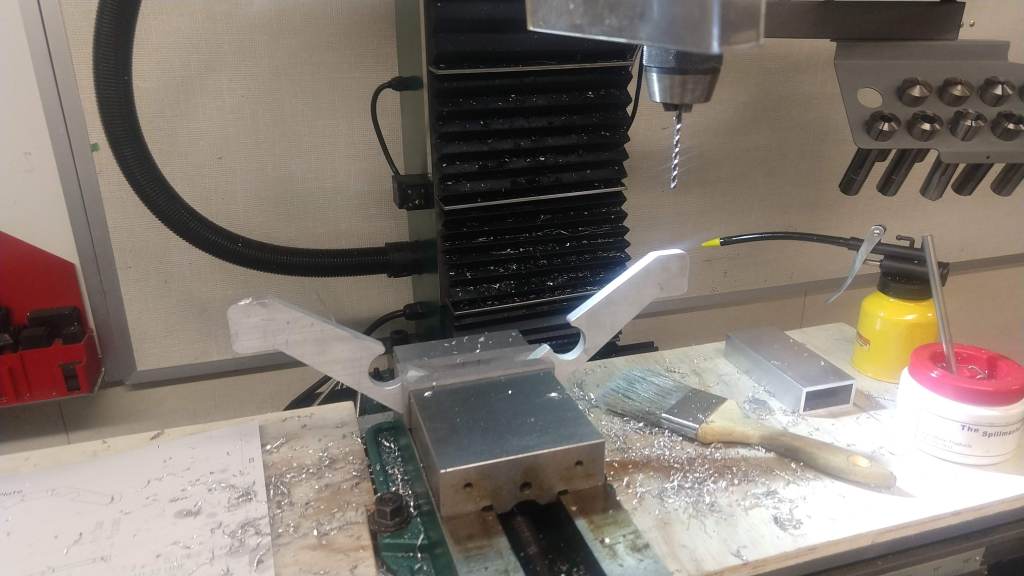
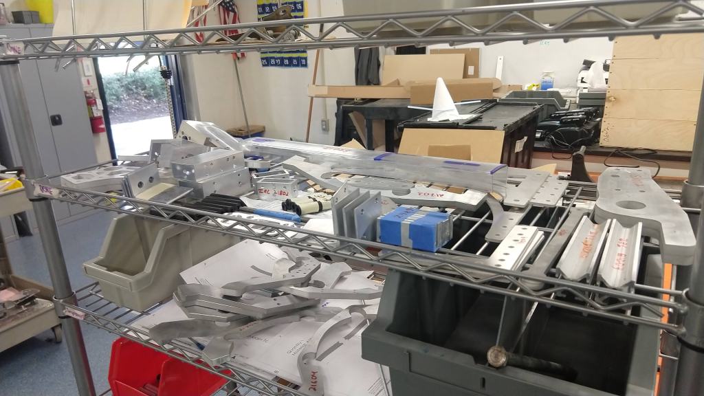
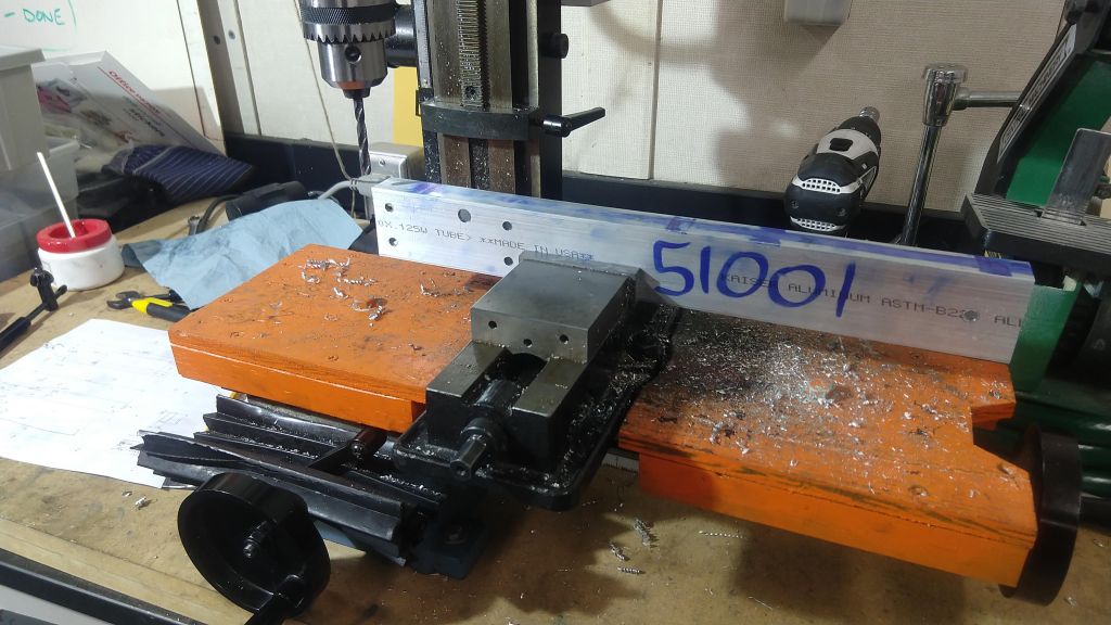
Pictures of the WIP intake prototype, the completed parts shelf, and the mill drilling a hole in the tube angled pieces.
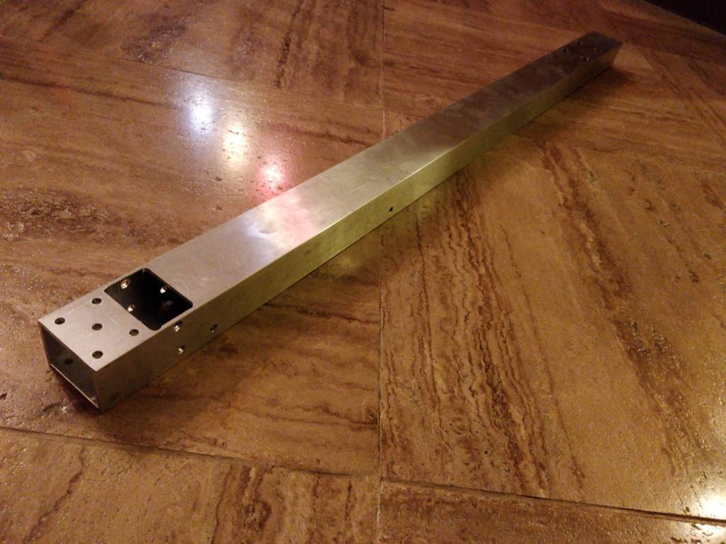
One of our climber beams and the plates we will use to assemble the intake and tube tomorrow (the orange is just a film we will peel off later).
Finally, we made some additions to our tracking spreadsheet so that we can see a breakdown of parts for each subsystem. It isn’t a complete representation of the progress, though, because some amount of 10 small parts might take half the time that it takes to make 1 hard part and you can’t completely capture that on the spreadsheet. It does give you a general sense though.
The part progress of our various sub-systems as of 2/7/20.
Every day the robot seems to slowly come together bit by bit. At this point we have about 58% of the robot parts completed. We finished one beam for the tube and should be able to finish the second tube tomorrow. We hope to get plates (out of lexan so we can test out variables) for the tube (and shooter) and intake either tomorrow or on Saturday. We also need to tap a bunch of holes in about 10 pieces (2 holes each), which will not take a short amount of time. Since we are getting 8 hours to work on Saturday, we should be able to definitely finish the tapping and also have time (and all the parts) left to assemble the tube and intake onto the robot.
We should also be able to have some build kids prototype an intake from both sides. This would mean it would be able to actually center balls and we would throw a couple at it (we now have 7 balls for testing and driving) at the same time to see if jamming would be a problem with the mecanum roller concept we have right now. If it is, we’ll adjust accordingly.
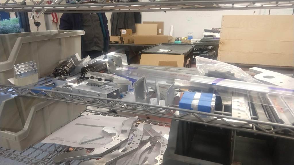
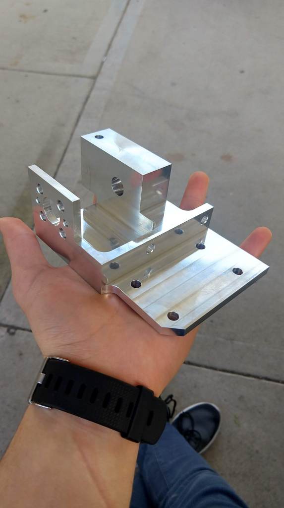
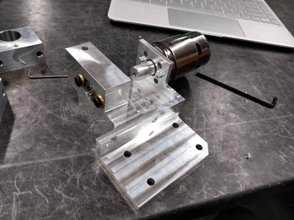
One very complex part we received today from one of our sponsors with and without the motor attached to it.
The pieces we have completed on the left, followed by some pictures of parts we are currently working on using our two mills.
At the same time electrical will be working on the electrical plate and should hopefully finish on Saturday as well so that they can wire the robot (or what is built of it) after we assemble it on Saturday. If for some reason the building goes late and electrical doesn’t have time to wire, we should still be able to get that done by the end of Monday so that Software has plenty of time to test and adjust.
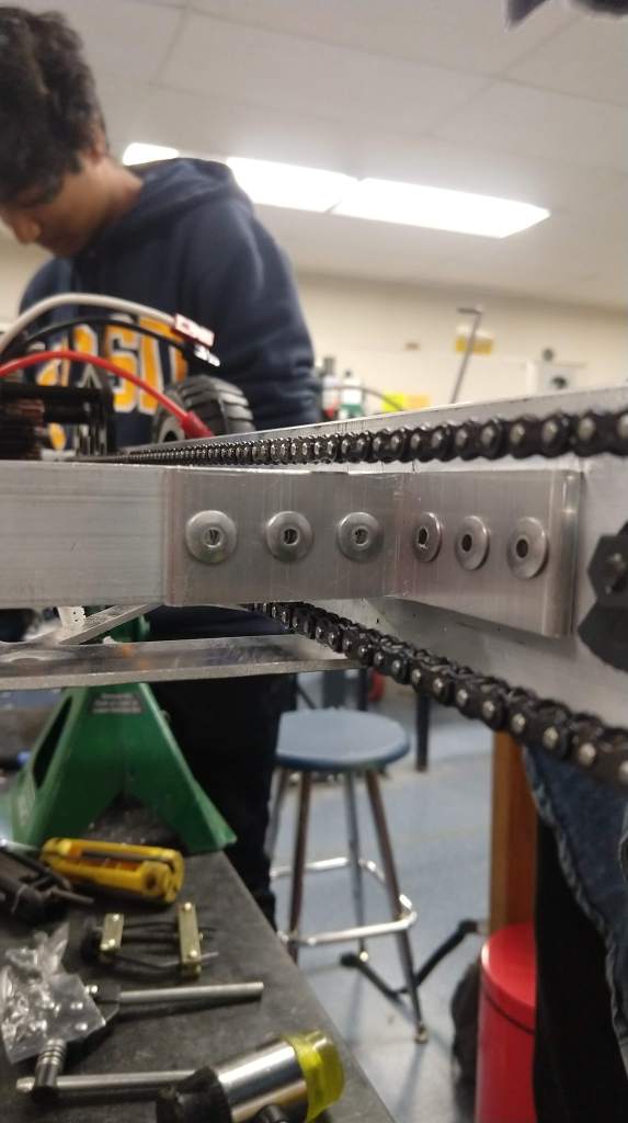
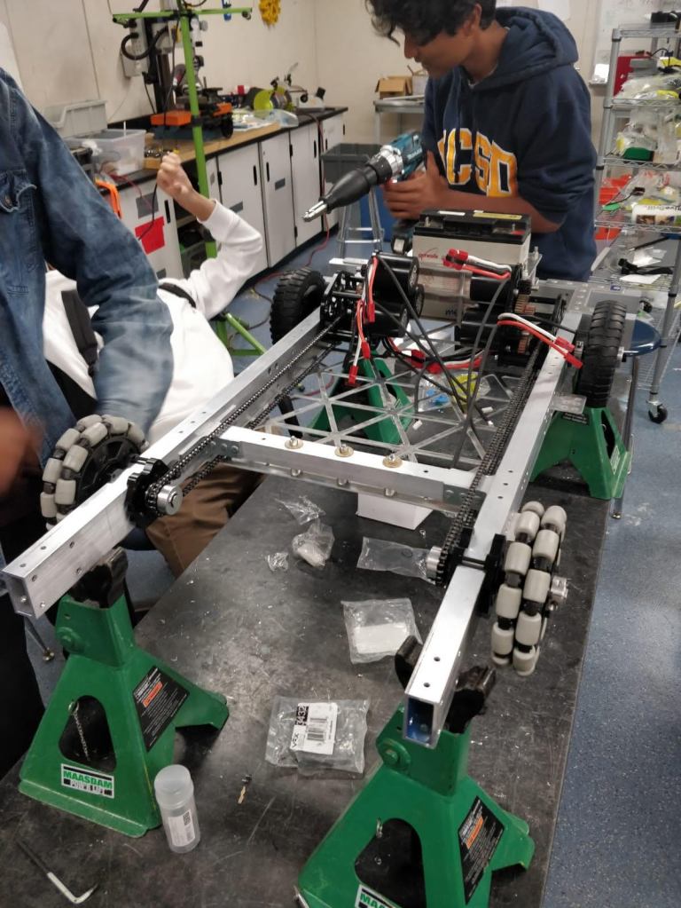
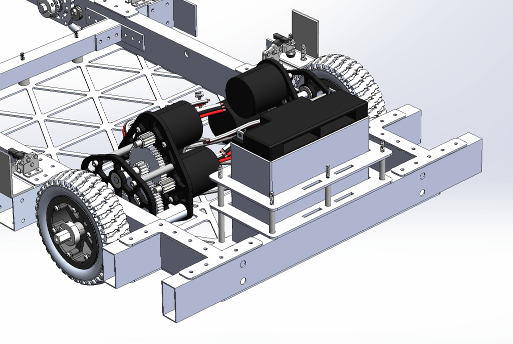
The drivetrain was completed on Monday (February 3rd) and it worked out flawlessly. We easily got it assembled with the brackets on top and drilled out holes on the bottom of the baseplate to use for rivet attachment. The gearboxes, chain, and wheels work together as planned and it all fits together perfectly. A couple of small things need to be added, but the drivetrain is basically complete.
Here you can see the chain’s gap over the front beam, the complete drivetrain, and the secure battery holder for this year.
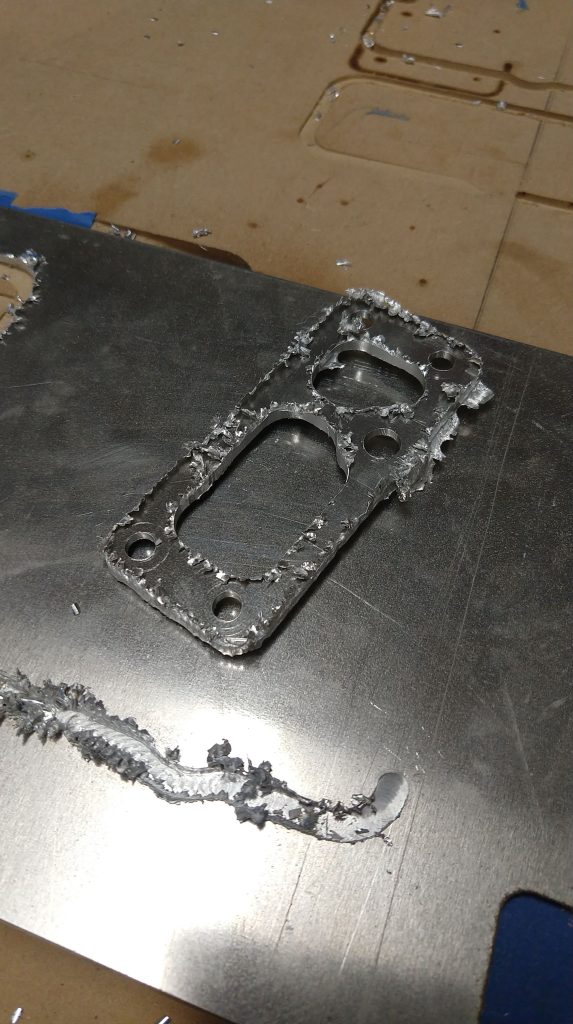
Yesterday and today we kept working on more parts for the robot. We’ve been spending some time over the past couple of weeks working with the CNC and figuring out its intricacies so that we can use it more for the robot. We still haven’t mastered it and continue to encounter some problems, but we were able to figure out some things that work today and get our first piece done. The first complete pieces technically came out very wrong and as a result of a problem with the cutting, but we were nevertheless able to clean it up and get it ready for the robot. We will continue working on getting the CNC ready for more parts and, when we get it working, we’ll be able to have some quick turn-around time on some parts.
A picture of the misshapen part. The bad cut is a result of some various problems but, we were still able to make this piece work with some clean up.
Build has also started working on the electrical plate today. That was finished before the meeting and electrical has started working on adding components. We should be finished with that soon enough so that we can wire the drivetrain at the very minimum (and let software start testing).
A picture of the electrical plate (technically plates) assembly without the actual components on.
As we look forward, we’ve slightly modified our plan. Because of the complexity of the robot and the sheer amount of parts we have to make, we won’t be able to finish the entire robot by Sunday. However, we still hope to be able to wire and assemble the tube and intake sub-assemblies onto the robot by the end of the weekend. That way, software should still be able to begin testing the shooting alignment and autonomous at the beginning of next week. At the same time, we will be able to assemble the whole elevator off the robot and attach it to the robot in less than 30 minutes.
To meet the deadline of Saturday for the tube and intake, we need only complete two side beams (one of which is halfway done) and get some waterjet plates. We will be working eight hours on Saturday so it definitely seems achievable. At the same time we hope to be able to use the initial versions of those sub-systems (which will be made out of lexan instead of metal) to test some uncertain parameters (like ball compression and intake extension) and modify quickly if needed. More blog posts to come (and hopefully pictures of more full assemblies) within the next couple of days.
Over the past couple of days we’ve been finishing up drivetrain parts and working on a couple of other parts. We also sent out large orders to a couple new sponsors and waterjet as well. We should hopefully get those parts towards the middle of end of this week.
In house, however, we were able to finish the parts necessary for our drivetrain today. Unfortunately, we were unable to get it assembled as was the plan because we did not have enough people to come to the meeting. We were able to quickly put on the baseplate using mock-rivets (I don’t know if that is the actual name but that’s their basic purpose). Immediately we saw a gaping problem with hole alignment. After some analysis we can see that there was some mess-up in the waterjet part and the holes were misaligned. On Monday we plan on assembling the whole drivetrain by starting with the brackets on the top part first and then flipping the robot upside down to attach the baseplate.
Here you can see the semi-assembled drivetrain. All the holes that lined up have a mock rivet in them (as you can see, not many).
Build has, as I said before, also had some progress on other smaller parts. Today we were also able to add bumpers to our list of things completed. As of now, parts simply take lots of time and progress is slow.
All the completed parts (so far) and the completed bumpers can be seen above.
We had a good amount of progress over the last two days. I also forgot to mention a few things in my 10-day recap post from the 28th, so I’ll put those down at the bottom.
Build continued to work on pieces and were able to complete four more. We now have seven pieces completed and still around 37% of pieces in progress. Some of the mill pieces for the drivetrain were finished although there are still more to complete. We should get a good amount of pieces (and hopefully the full drivetrain assembled) finished over the weekend as we have a lot of time to work. In addition, some slight hitches with CNC will hopefully be ironed out tomorrow and, once we are able to ensure that pieces be made safely and effectively on the CNC, we will be able to use the new 1/8″ bits that arrived to make a good chunk of the robot pieces on the CNC. As usual, the plan is for the robot to be assembled by the end of next Sunday.
Electrical has started working on the electrical board and pneumatic systems and, if the parts ordered arrive on time, they should be finished. Depending on the build finish time (the way it’s looking from the sheer volume of parts to be made), electrical might have to wire the robot after next weekend. Although, if we are able to use our resources and time to our advantage, a full wiring is still possible by the end of next weekend.
Software has the drivetrain code completed and is working on operator controls as well as some basic tracking for the port and balls. They are now also working on rudimentary autonomous. In theory, we should be able to have a good autonomous using simply our encoders and pre-programmed instructions. However, it would be nice – and this is the goal we are striving towards this year – to have an autonomous mode that uses limelight and sensor input to be able to continue driving and scoring based on what it’s already done. That would allow us not only to use the full fifteen seconds to our advantage (as opposed to just shooting three balls in and stopping for ten seconds) but also to hopefully score more points.
Marketing has finished first drafts for the chairman’s presentation and Woodie Flowers essay and will be reviewing tomorrow. They will also finish the first drafts of the Dean’s List essays during the weekend so that there is sufficient time for review of all the awards.
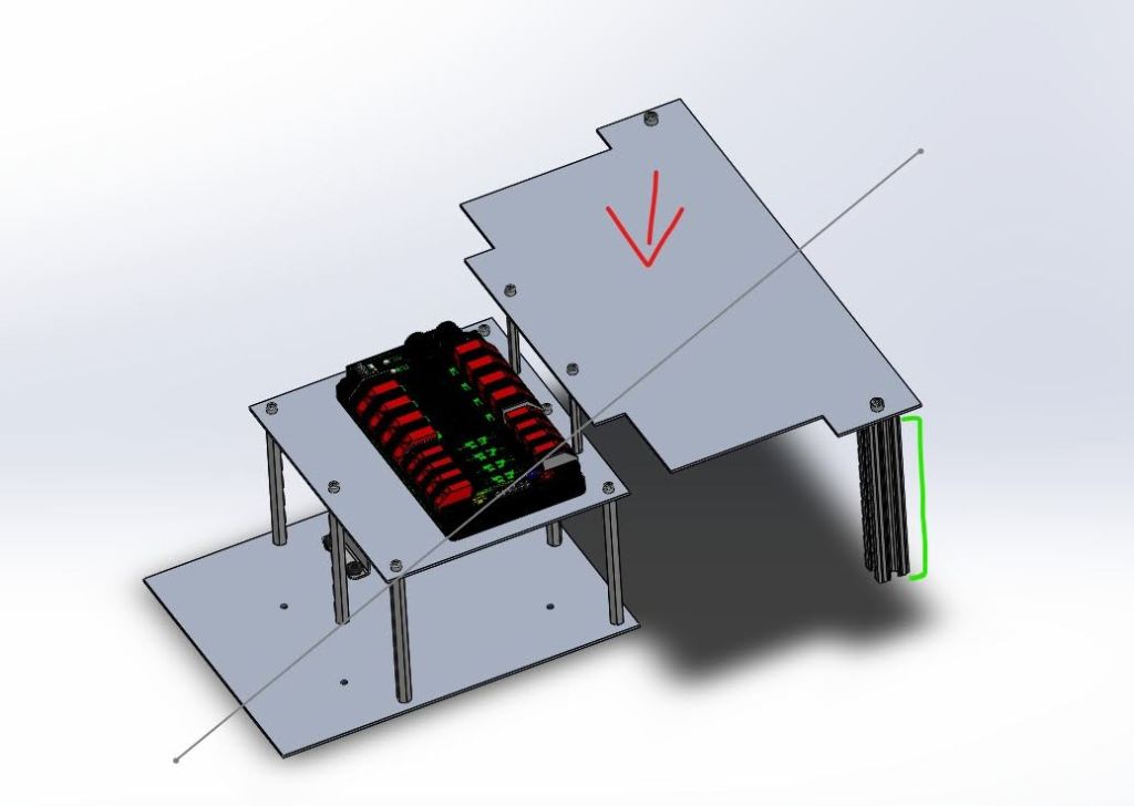
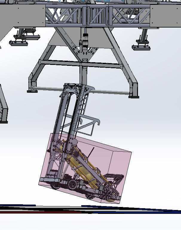
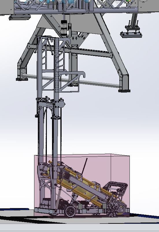
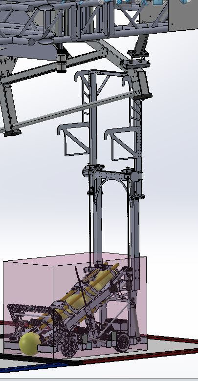
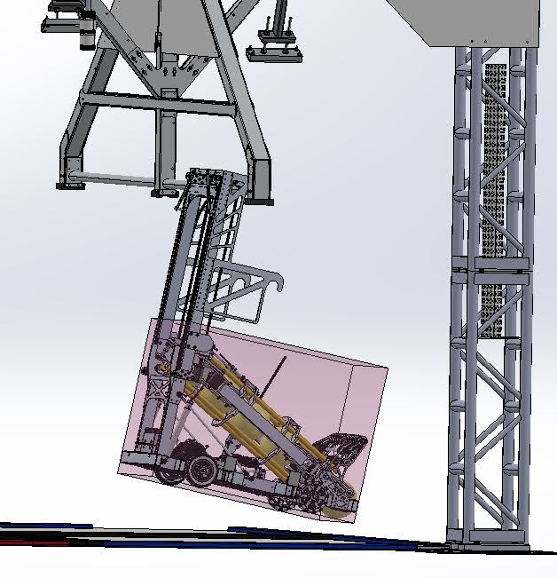
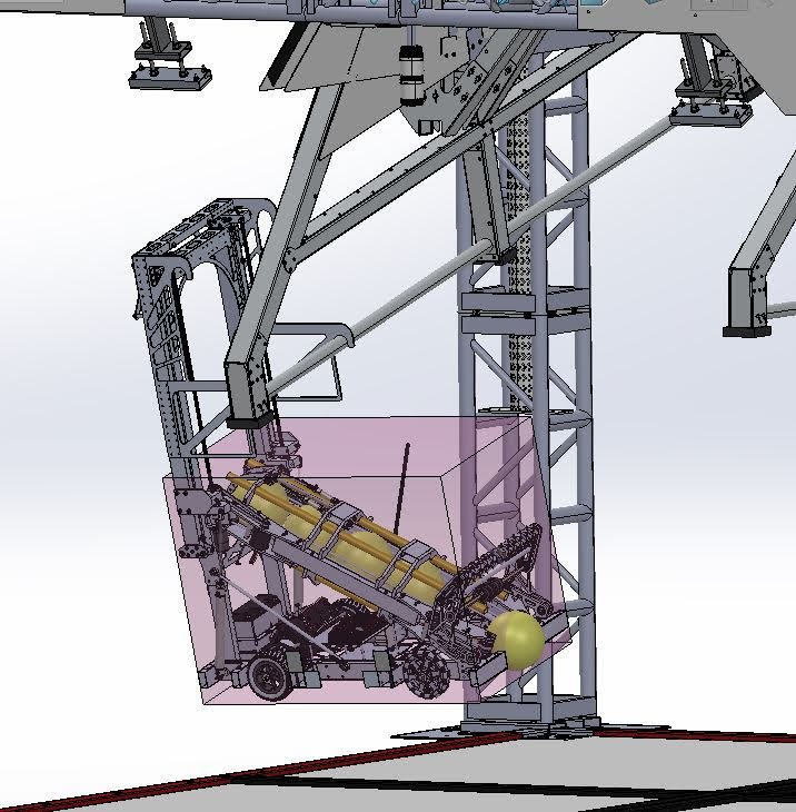
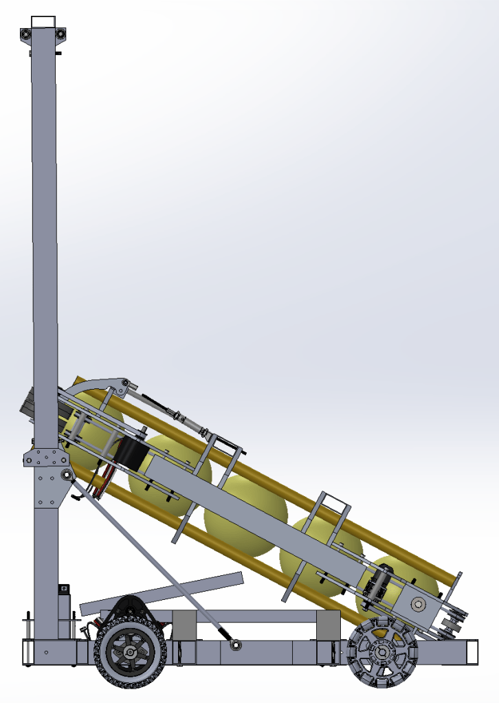
As I said before, there are a couple of things I forgot to mention in the recap. One of them was a collection of handy pictures of the robot climbing (in the CAD). As design finished, Beni was able to capture all the possible robot climbing configurations and make sure they work and that we can climb.
Pictured above you can see every possible climb configuration for our robot.
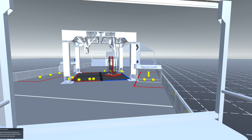
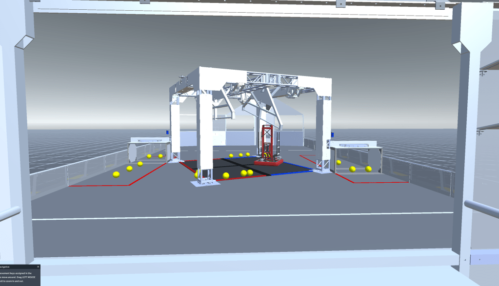
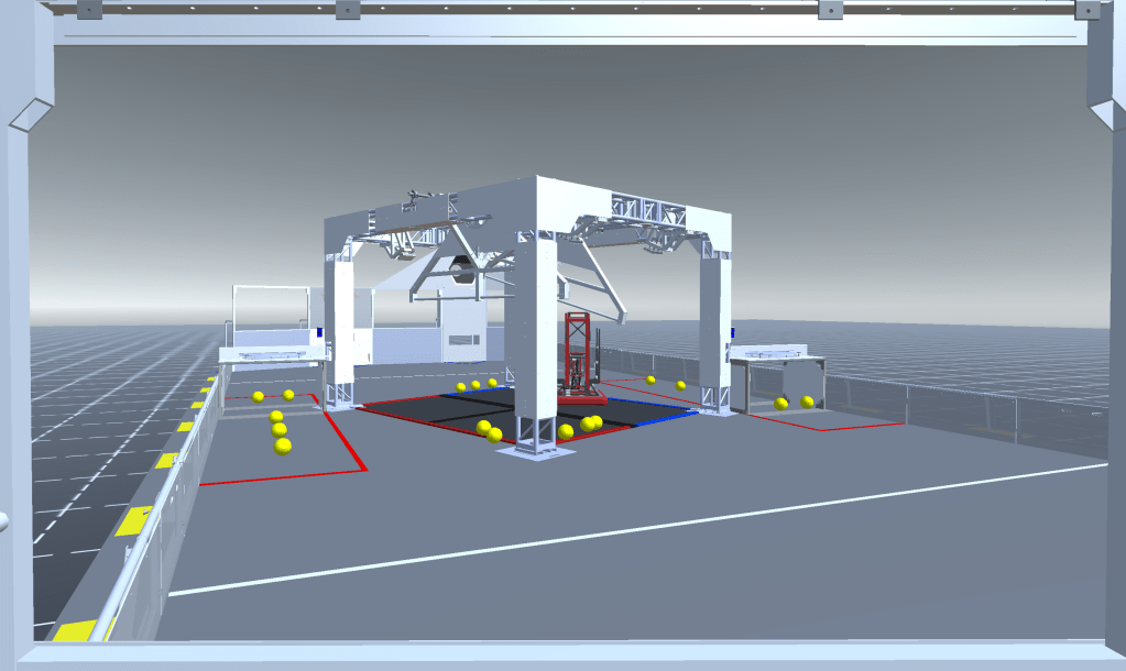
I also opened up a program called Synthesis which lets you input robot CAD and code and test it virtually on your computer. From there I could get a somewhat realistic representation of the view that we would see from each driver station.
The view from each driver station with a sample robot loaded in the middle.
From the three views we can see that the drive team view of the port is very minimal if visible at all and that the angle at which we view the scale is definitely not optimal. This would mean that, in order to be relatively effective at scoring and climbing, we would most likely need an automated adjustment system for shooting that uses limelight to align as well as an adjustment mechanism for the scale that would let the drive team have greater error in lining up for the climb.
The last thing I forgot to recap was our work with the intake prototype. We tested this out last Saturday when we got the 2″ mecanum wheels from West Coast Products. These proved to be difficult to work with due to their limited slanted roller coverage. This meant we needed to bunch them up very closely for the slanted rollers to have coverage on the ball. We also had some trouble with actually getting the mecanum wheels to center the ball. Below you can see the problem we had where they would essentially act as normal wheels and squish the ball to intake it.
The mecanum wheel problem we had for pretty much all of Saturday.
Every once in a while we would get the intake to kind of work, but this success was usually very short and the results could not be replicated. Below is one instance where we saw the intake working.
The intake seems to work for a bit, but then reverts to the problem in the video before this.
We ended Saturday pretty disappointed but hopeful for what the new mecanum wheels (which we had marked as superior to the WCP ones and which we bought on Sunday) could bring us. And, lo and behold, when the new mecanum wheels arrived on Wednesday, our intake somehow magically worked. For one, the better slanted roller coverage allowed us to spread them farther apart and still have good coverage on the ball. In addition, we got the spacing pretty good and the intake seemed to work well. Below you can see it with the new wheels, spaced out quite a bit.
The intake working for the first time.
As you may have noticed, the last two ball throws bounced off because they hit a bit of a dead spot in the intake. We were easily able to resolve the problem by bring the wheels slightly closer and basically eliminating that dead zone while still keeping some distance between the wheels. Below you can see the revised (and so far the best) version we have right now.
The intake at its best.
The primary purposes of building an intake prototype were to make sure the concept works and to make sure balls don’t jam when we try to pick up multiple at the same time. We should hopefully be getting more balls within the next couple of days and, when we do, we will test out the possibility of jamming. Although this won’t be a perfect representation of the robot geometry, it should still give us a good idea of what we have to work with. You can see full videos of the intake (the ones above are only small clips) in the photos/videos album on the front page.
That basically concludes the recap from the past ten days and the progress from the last two. There will be more blog posts over the weekend as the teams come in to do their various jobs.
Apologies for the very long time gap between posts. I’ll try as much as possible to capture all the progress since the 17th in this post.
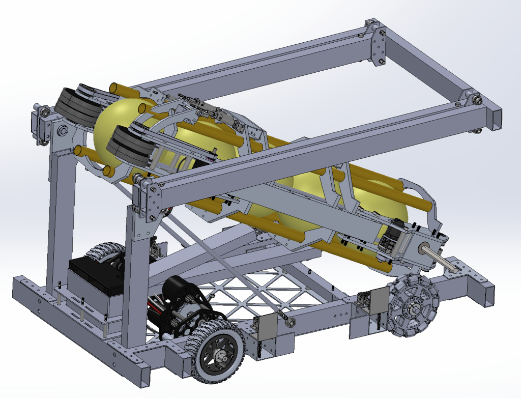
Design was able to continue working on the various sub-systems throughout all of last week and, since Sunday night, are now done with the design of the robot. A few small tweaks are being made but other than that, most of the robot parts have been ordered and many have already been received. Another thing to mention is that the color wheel mechanism still hasn’t been implemented but that should be an easy addition. As for sticking to the timeline, design was not able to adhere to the various milestones for sub-system completion despite being able to finish the whole robot on schedule. This should set back the individual subsystems but not the entire robot. Essentially, we should be able to stay on track, but things will be done more in bulk than by subsystems.
Pictures of the finished robot CAD as of now. Color wheel and climb adjustment mechanisms will be added soon.
Build started working on pieces for the robot on Monday (January 27th) and will be able to, with increased member attendance, start churning out parts at a quick pace so that assembly may start mid-next week. Currently about 36% of the pieces needed for the robot are in progress and being built using either the mill, CNC, other tools, or our waterjet sponsor. Three pieces so far have been finished and many more will soon follow. Unfortunately due to some sponsor setbacks we do not have a drivetrain assembled and are just now starting on some of the pieces for the drivetrain. Ideally those pieces will be completed shortly and the drivetrain assembled in no time, but it is possible that the sponsor delay sets us back a few days. Overall, with some increased effort and dedication in the next two weeks, a full robot assembly date of 2/9 still seems doable but considerably more difficult.
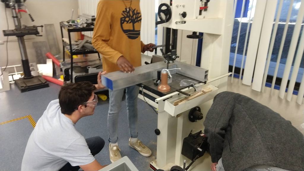
Pictures of the build team hard at work on their parts.
Software has been able to write some code for the drivetrain and are beginning to write code for other subsystems as well as explore some various autonomous options. Software is quite behind on the autonomous but, as with build, a “comeback” does not seem out of the question. It is now a matter of the dedication and time that the team will put in the next three weeks as they finalize the code and test it (hopefully) starting 2/10.
Electrical components for the robot were ordered today and as soon as those arrive the team should start assembling the electrical board and pneumatic systems.
From a marketing standpoint, we should see first drafts for all our awards (Dean’s List, Woodie Flowers, and Chairman’s) tomorrow at the meeting and shirts will be ordered then as well.
Finals week just finished and we should be able to ramp up productivity on some missed deadlines (most notably finishing the field elements and working on autonomous). However, this past week was not void of progress.
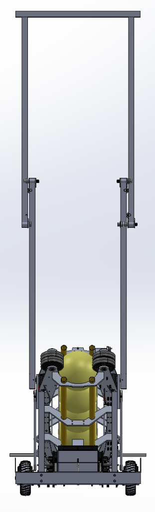
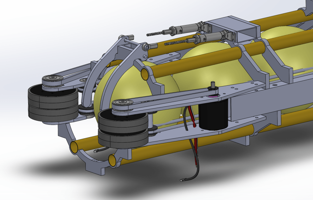
Design-wise, a considerable amount of progress was made on the elevator. The primary structure is in place but motors, climb attachment, and some extra details still need to be worked out. Some initial block-modeling for the linear actuator for the tube has also begun. Design should be able to meet the Sunday deadline for the finalized second mechanism and have parts ordered soon thereafter.
Pictures of the elevator in different positions. Underneath the tube you can see the initial block-CAD for the linear actuator.
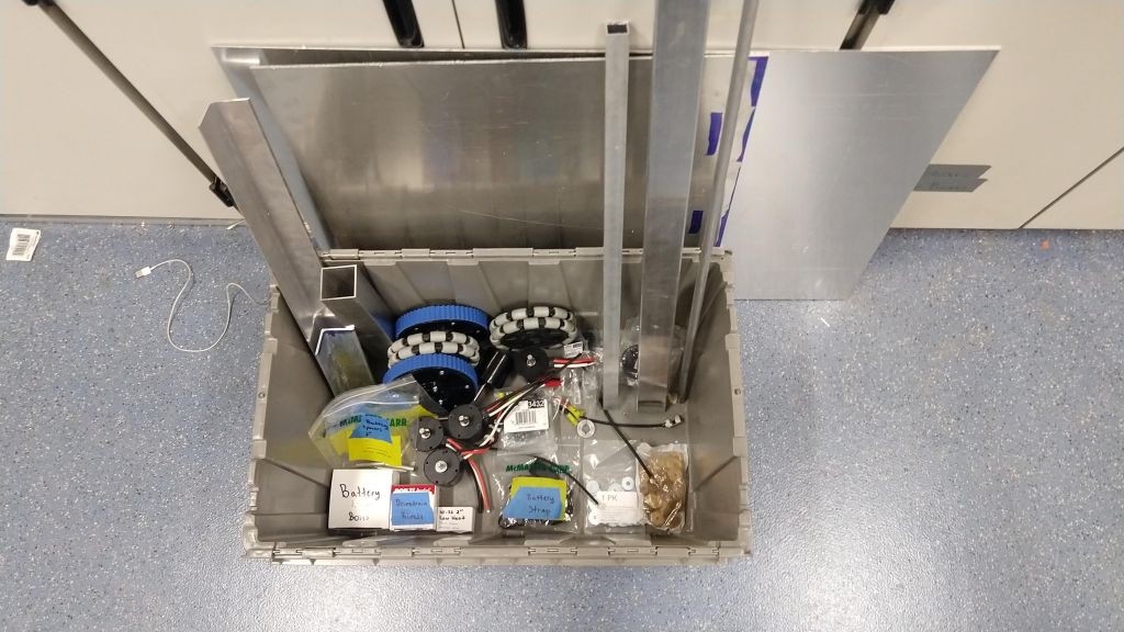
Drivetrain parts were ordered and most were received. Some 2×1 tubing and aluminum sheet metal was sent to our waterjet and milling sponsors for precision work and we should receive that back soon. As soon as Build gets those finished pieces assembly should commence right as planned.
The drivetrain parts we have so far clearly labeled and organized in a tote in the build room.
Although they only met for a brief window earlier this week, build was still able to attach the lowest hardstop for the shield generator. Some adjustment may have to be made but it seems generally good for now. As for what should be done over the weekend (or first thing when we come back to school if we aren’t able to secure time to work over the weekend) would be the top hardstop for the shield generator as well as completing the leading bay with it’s curved pieces. Once that is complete, build should be right on track and free to work on prototypes until the drivetrain pieces come. Once we start working on the robot we should still hopefully have a small team ironing out details and iterations of sub-assemblies with prototypes.
A picture of the bottom hardstop for the shield generator.
That’s all for now but we should hopefully have more of these updates as we move faster through the robot process.
Although most of the team is out for finals week, there are just a few notable updates concerning our progress. In design, a couple of small additions were made including a holder mechanism on the end of the tube (so that the balls don’t automatically get shot) as well as a battery holder for the drivetrain. Drivetrain parts were ordered and special parts to be milled and waterjet (from our sponsors) were also sent. We anticipate for them to take about a week (or hopefully less) to arrive.
Pictures of the battery holder and added stop for the ball at the end of the tube.
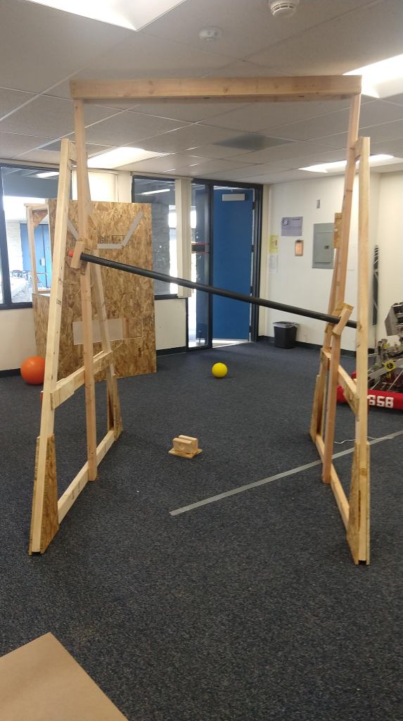
In the meantime, build will be working on the leftover drivetrain pieces with the materials we have and once we get the rest, we’ll finish that up soon. Design-wise, drivetrain is right on schedule and if the shipping is according to our planning, build should be able to be right on track as well. As per the field pieces, build is still lagging behind. They were, however, able to add the level and minimum position hardstop pieces for the shield generator. This should allow us to start prototyping some climbing adjustment mechanisms. If we spend some time working on the weekend, build should be able to completely finalize the field pieces as well as set up the room for driving.
Pictures of the shield generator assembly at the level minimum hardstop.
Slight side note: the room is a bit small. Essentially, the distance between the color panel and the power port is too large to be able to fit them both within the room. In addition, the top power port does not fit within the room. On top of that, the distance between the shield generator and power port might also be too big to fit within the room (has yet to be measured for sure). So, we will probably have to practice with a shorter distance between the shield generator and color panel as well as wheel out the robot and power port when we have to practice shooting. There is a decent open space right outside the room without a roof where we might be able to lay carpet and put up the whole port assembly but we wouldn’t be able to practice with the rest of the elements. Nevertheless, the central point of all this is that the driver practice experience will be considerably different than the actual one so we must have that in the back of our mind when practicing.
Looking forward, build should start working on some updated shooter prototypes and some new climber prototypes and software should hopefully be able to spend some more time working on autonomous and limelight tracking after finals. Design will hopefully keep pushing on with the good CAD work and electrical should hopefully have a nice period of time to rest. Overall, there are a couple of setbacks (like a somewhat disorganized build room and slightly lagging progress with build and software) but with some more work after finals, we should be able to be right on track for success.